
How To Create a Pressure Sensitive Pad or Switch
Back to Application Notes
Introduction
Mechanical buttons and switches have been used since the dawn of modern electronics, but they are starting to be replaced by modern alternatives that reduce the size, mechanical complexity and improve operational life. Capacitive force sensors are an excellent substitute for a switch as they can be made in a wide variety of sizes offering a sleek, modern user interface. They can be programmed with an optimal detection force for triggering, removing the blight of false activations prominent in their cousins, proximity sensing pads. They can even be used as a proportional force input sensor, adding additional continuous functionality to a typically binary media.
The following video gives a great example, developed by our colleagues at PPS:
The video compares different input media, illustrating that the capacitive force-based binary switch has the same low profile as the capacitive proximity switch, but with no false activations whilst maintaining the threshold activation of the mechanical switch but with a much longer cycle life.
If binary inputs are no longer cutting it for your application, why not try a force proportional input? This approach gives you the flexibility of a physical dial, with the low profile of a capacitive sensor, giving your products a sleek and flexible user interface.
Interested? Keep reading to find out how to implement these in your own projects!
Using SingleTact As A Pressure Sensitive Switch
Interested in a sleek, robust, user interface for your product or project? Here is how to do it!
We begin by selecting an appropriate sensor for your application, you can find out more about how to do that on our helpful guide. We then connect the sensor to the PC, and then describe the signal processing required to get you started. We will look at the plug and play version first, but these methods can easily be applied to embedded solutions for low level integration into your projects.
A 10N, 8mm USB SingleTact provides an excellent PC based development system. It is plug and play, the right size for a button and has a force range suitable for a medium force button press of 5N. Alternatively, you may wish to skip straight to the embedded solution using a standard SingleTact electronics module detailed below.
Connecting The Sensor And USB Board
Don’t want to read the instructions? Don’t worry, we have a video below!
1. Pull out the Sensor Locking Tab gently (it will only move about 2mm)
2. Insert the SingleTact Sensor into the FFC Connector, matching the orientation shown in the diagram below.
3. Push the Sensor Locking Tab back in
4. Insert the supplied USB Micro cable into the USB Micro Connector
5. Plug the USB cable into an available USB port on your PC or laptop.
To test that your SingleTact USB board and SingleTact pressure sensor are connected correctly, lightly press on the sensor face with your finger. You will see a red LED light up when you load the sensor. The brightness of the LED is proportional to the applied load.


6. Download and install the acquisition software. Run the software with the sensor plugged in and you should see the output trace respond to pressure. If you have any problems, see more details in the USB Quickstart Guide.
The video below shows the whole process:
Creating A PC Demonstration
There are multiple ways to do this, but the easiest by far is to use our PC demo app. You can get a Windows installer from our ‘Resources‘ page. You can also download the standalone installer for the demo visualisation app as a Windows app, simply search ‘SingleTact’ on the Microsoft store. The app is limited to displaying and saving your sensor data, but serves as a very useful building block for integration into your own projects.
The SingleTact PC demo application (C# .NET) and Arduino code for embedded solutions are open source, available from our GitHub. We recommend Microsoft Visual Studio 2019 for development and cloning via Git, if you wish to use it as the basis of your own software.
There are 3 projects in the solution from our GitHub:
SingleTact Interface – An encapsulated interface to the SingleTact. This is used by the other projects
SingleTact Demo – The source for the SingleTact DAQ software
SingleTact Barebones – A very simple ‘hello world’ example
SingleTact Barebones is a great place to start prototyping your own user interface.
The SingleTact will output 0 – 512 for the 10 N range. Therefore an output of 5N corresponds to a ‘medium’ button press.
Once you have your SingleTact up and running, we can now implement a button!
Creating A Binary Button
This section describes how to apply signal processing to your tactile data to implement a binary button as a user interface. Of course, you can use the force output directly to create your proportional force input, as we showed in the first video.
The simplest implementation would use a simple threshold for a button press, so:
Sensor output < 255 counts = off
Sensor output >=255 counts = on
However, if the user hovers around 5N, the button can turn on and off very quickly which is not ideal. It is preferable to build in some hysteresis separating the activation threshold from the reset threshold as shown below:
The code becomes slightly more complicated, but gives a much better user experience.
If (sensor output > SL and Switch is OFF)
Turn the switch ON
If (sensor output < RL and Switch is ON)
Turn the switch OFF
And that is it for creating a simple binary user interface!
You can see how some of our customers have implemented force sensitive buttons in their own projects in the image below!

You can easily apply this technique to your own projects, but the applications of tactile sensors as user interfaces are not limited to switches…
How about a continuous joystick?
Creating A Flat Joystick
Button presses and even a proportional button not quite right for you? You can create your own low profile joystick using SingleTact, and we will show you how!
Or, do you ever feel disappointed when you press harder on a controller and you don’t move faster, or hit harder in a game? Try SingleTact sensors for your joystick or button, where pressing harder gives you a bigger response you can use to control your project or product!
Three sensors can be positioned in a triangle to create a simple low profile joystick. Putting a small rigid disk over the sensor distributes the load over each of the three sensors. The X and Y-axis values can be calculated from the centre of pressure calculations shown below, where Xk, Yk is the location of sensor k and Sk is the sensor output in counts. This can easily be converted to an angle, should your project require that. You may also want to add a minimum force threshold to prevent accidental activation, this is similar to a ‘dead-zone’ in traditional joysticks.

It is as simple as that. With a little bit of creative sensor placement, you too can have a sleek and low profile user interface for your product or project.
Embedded Solution
While the high level USB electronics may be ideal for some projects, we understand that some applications and designs require a lower level interface that you can integrate with embedded systems and microcontrollers, rather than a PC. This is useful if your project is standalone and doesn’t use a PC, or if you need to combine inputs from multiple sensor systems together (SingleTacts and any other low level sensor you may have in your project) before sending the data to a PC.
The standard SingleTact electronics come with an I2C interface and an analog output. This combined with a 10N, 8mm sensor makes an excellent button, using exactly the same signal processing steps as outlined previously.
You can apply all of the steps outlined above, using the demo app if you wish by using the SingleTact example Arduino interface, available on our GitHub which is compatible with the demo app for a single sensor interface.
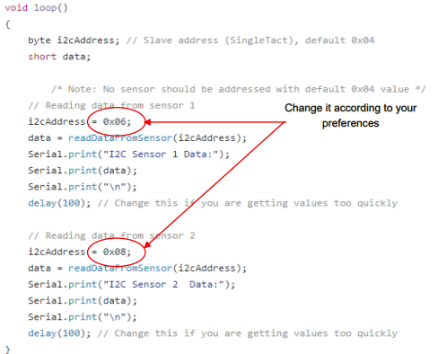
Application note 2, gives an example of interfacing between multiple SingleTact sensors and an Arduino over I2C, including code snippets, as shown below. Of course, any microcontroller can be used.

Summary
This application note showed how a SingleTact can be used to create a simple pressure-sensitive pad or switch. This note covered the electrical and software interface, mechanical considerations are covered separately in this application note.
SingleTacts and other components are available from our online shop.
If you are interested in OEM integration, engineering support or custom sensors sizes please contact our colleagues at PPS (the technology developer of SingleTact).
Good luck with your project using SingleTact!